Quick Change System
Hydraulic Liner Retention System
Explore an illustrated hydraulic preload and mechanical locking sequence. This concept animation is not an installation guide or a verified model-specific assembly.
Hydraulic liner retention — concept animation
Simplified fluid-end side view. This is not a model-specific assembly or installation guide.
The illustration identifies a fluid end, liner, retainer, hydraulic actuator and hand pump. Actual parts and load paths depend on the selected assembly.
How to review this system
The illustration separates hydraulic preloading from the mechanical locking step. The sequence and required tools must be checked against the chosen system instructions.
Liner, retainer, lock ring and fluid-end geometry vary. A similar appearance does not establish interchangeability or sealing performance.
Required pressure, tightening method, inspection limits and change-out time are model-specific. Do not derive them from animation scale or timing.
Request the exact bill of materials and installation document for the proposed configuration before placing an order.
Related product references
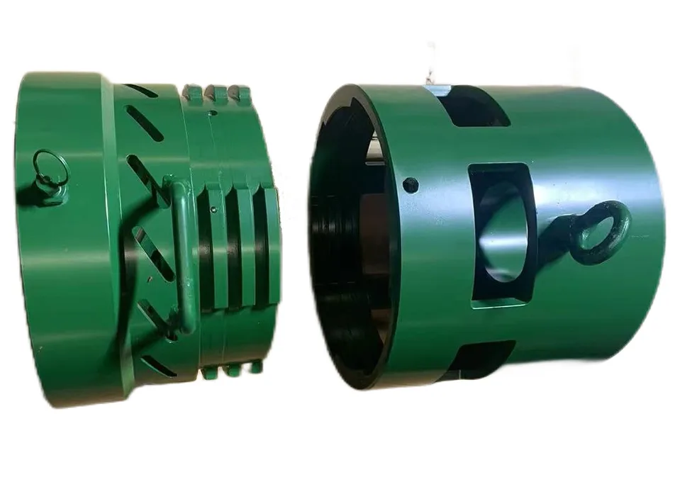
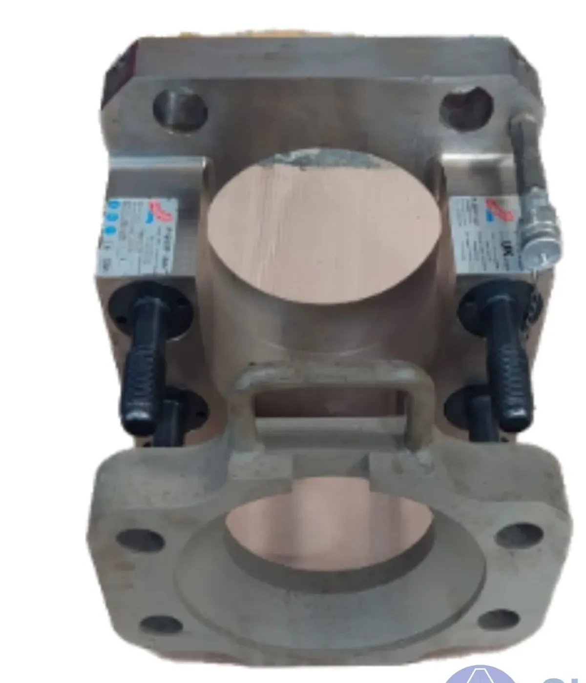
Review the two listed system references. Availability, supplied components and compatibility require a separate technical and commercial confirmation.
Common questions
- Does it fit my pump?
- Please provide the exact pump and fluid-end model, serial or configuration details, and the existing liner and retainer documentation. Fitment remains pending until the proposed parts are checked against those sources.
- What holds the liner after pressurization?
- The animation depicts a mechanical locking step after hydraulic preloading. The actual load path and depressurization procedure must be verified in the manufacturer instructions for the selected assembly.
- What comes in the package?
- Contents vary by configuration. Request the proposed parts list, installation instructions and commercial offer before assuming that a pump, hose, gauge or seal kit is included.
Send the pump details for a technical review
Include model, serial or fluid-end configuration, existing part references, photos and required quantity. We will review the evidence before discussing fitment or supply.